Use NPN (Not Pointing iN) transistor to build a single stage amp
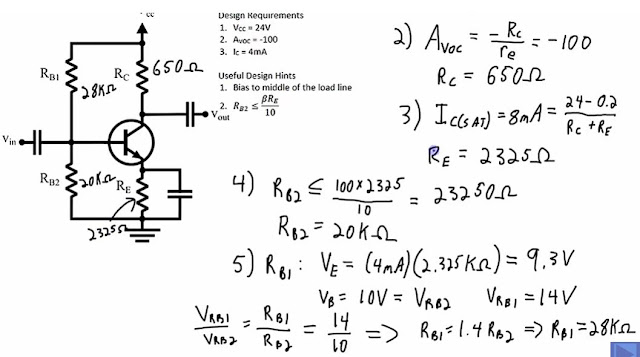
- Voltage Divider Rb1 28K and Rb2 20K
- Emitter Degeneration Resistor Re it megates the non-leanarities of the transistor and it works with the bias circuit.
- Rc and Re are Collector Resistor and Emitter Resistors
- Bias at the middle of the AC load line (Vce =12v half of Vcc; Ic saturate = 8ma (2x 4ma)
- Common Emitter Amp - when the input goes +ve positive the output goes negative -ve
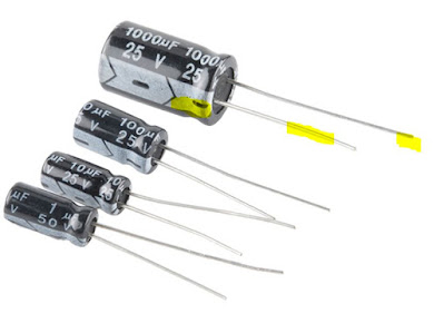
- Electrolytic Capacitor the +ve positive lead is longer than the -ve negative lead. Also the Stripe painted on the body usually denotes the nagative lead
Small Signal Common Emitter Amplifier
The voltage at the collector will be 1/2 of Vcc to give the proper headroom for the waveform, if the bias is too high, it will clip the top of the waveform and if it is too low, it will clip the bottom of the waveform. you will not have headroom for the swing of the output waveform voltage. This is the Q point when the signal is at crossover or the amp is idle. No signal.Example (see Diagram below)
Rc = 1/2 Vcc , the lower the value of Rc the higher the current. eg 4.7K ohm resistor. so Ic = 1/2 Vcc/4.7K ohms = 1.37mA
So approx 1.37 mA will flow thru the emitter circuit also.
Gain = Rc /Re, so if your gain is 100, and Rc = 4.7K, then 1/10 of Rc = 470 ohms.
Calculate the Ib = Ic/beta = 1.3mA /100 = 13uA
Voltage divider current is typically 20 x current at Ib, so 20 x 13uA =260uA
So the sum of the 2 Resistors Rb1 and Rb2 of Voltage divider = 24volts/260uA = 46 K Ohms
Rb2 = Voltage Drop across Re (470 ohms x 1.3mA) + Diode junction drop of Base Emitter voltage (.65volts) = .61Volts + .65volts = 1.26Volts.
So Base Emitter Junction voltage is 1.26Volts.
From Ohm's law you can determine the Rb2 Resistor value = 1.26volts/13uA =4.8K Ohms
Now calculate Rb1 = 39K ohms
Capacitor input is a high pass filter equation
Ref: https://www.youtube.com/watch?v=9325TKD4dfY
Note Common Emitter Amp - when the input goes +ve positive the output goes negative -ve
Ref: https://www.youtube.com/watch?v=9325TKD4dfY
Ref: https://www.youtube.com/watch?v=EVekdy2_Dyw&t=10s
- Take out all the AC components - Short the AC sources
- Open Circuit all Capacitors - Disconnect source and disconnect load and bypass capacitor
- Simplify Circuit
- Find the operating Points
- What is the Collector Current Ic and
- What is Collector Emitter voltage Vce
Lets say Beta is 150 for the NPN Transistor
Rb2 is < 0.1 x Beta x Re
Short ALL DC voltages
Short ALL capacitors
Replace Transistor with an AC modle of Transistor
Simplify Circuit - Combine Resistors
Deternine AC Gain, Input Impedeance and Output impedence.
https://www.youtube.com/watch?v=DVLO4YBURSo


No comments:
Post a Comment