Sunday, June 30, 2024

Design Common Emitter Amp

 Use NPN (Not Pointing iN)  transistor to build a single stage amp

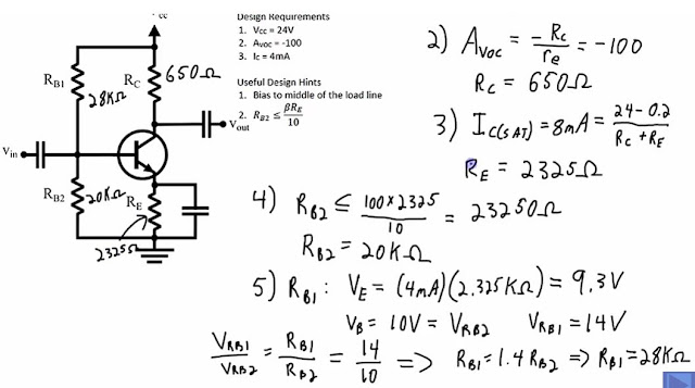
  • Voltage Divider  Rb1 28K and Rb2  20K  
  • Emitter Degeneration Resistor Re it megates the non-leanarities of the transistor and it works with the bias circuit. 
  • Rc and Re are Collector Resistor and Emitter Resistors
  • Bias at the middle of the AC load line (Vce =12v   half of Vcc; Ic saturate = 8ma (2x 4ma)
  • Common Emitter Amp - when the input goes +ve positive the output goes negative -ve
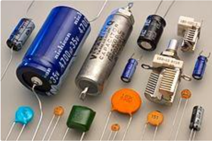
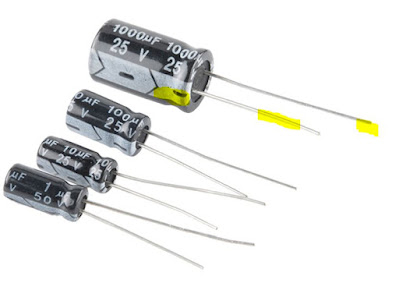
  • Electrolytic Capacitor the +ve positive lead is longer than the -ve negative lead. Also the Stripe painted on the body usually denotes the nagative lead 


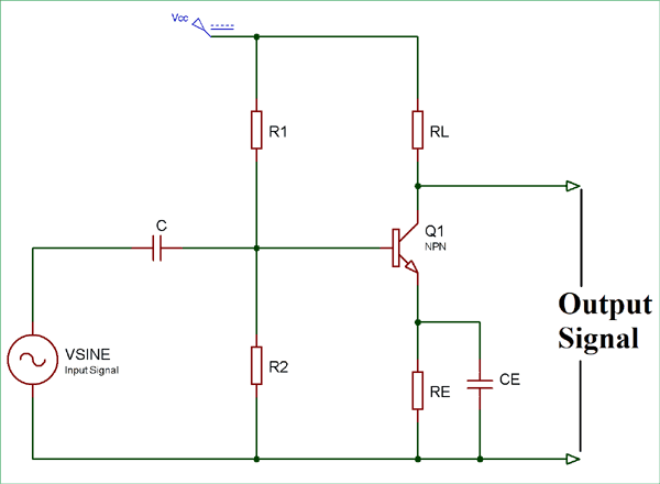
Small Signal Common Emitter Amplifier 

The voltage at the collector will be 1/2 of Vcc  to give the proper headroom for the waveform, if the bias is too high,  it will clip the top of the waveform and if it is too low, it will clip the bottom of the waveform. you will not have headroom for the swing of the output waveform voltage. This is the Q point when the signal is at crossover or the amp is idle. No signal.


Example  (see Diagram below)

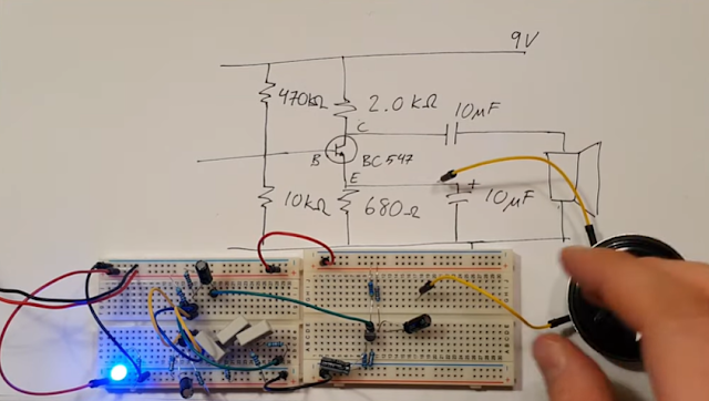
Rc  = 1/2 Vcc , the lower the value of Rc the higher the current. eg 4.7K ohm resistor.  so Ic = 1/2 Vcc/4.7K ohms  = 1.37mA

So approx 1.37 mA will flow thru the emitter circuit also. 

Gain =  Rc /Re, so if your gain is 100, and Rc = 4.7K, then 1/10 of Rc = 470 ohms. 

Calculate the Ib = Ic/beta = 1.3mA /100 = 13uA

Voltage divider current is typically 20 x current at Ib, so 20 x 13uA =260uA 
So the sum of the 2 Resistors Rb1 and Rb2 of Voltage divider  = 24volts/260uA = 46 K Ohms
Rb2 = Voltage Drop across Re (470 ohms x 1.3mA)  + Diode junction drop of Base Emitter voltage  (.65volts)  = .61Volts + .65volts = 1.26Volts. 

So Base Emitter Junction voltage is 1.26Volts.

From Ohm's law you can determine the Rb2 Resistor value = 1.26volts/13uA =4.8K Ohms

Now calculate Rb1 = 39K ohms

Capacitor  input is a high pass filter equation


Note Common Emitter Amp - when the input goes +ve positive the output goes negative -ve

Ref: https://www.youtube.com/watch?v=9325TKD4dfY


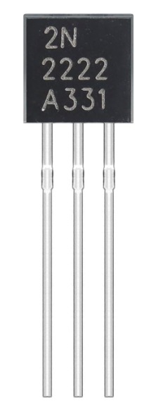
Transistor: 2N2222A, NPN 


Ref: https://www.youtube.com/watch?v=EVekdy2_Dyw&t=10s


For DC Analysis - 
  • Take out all the AC components - Short the AC sources
  • Open Circuit all Capacitors - Disconnect source and disconnect load and bypass capacitor
  • Simplify Circuit
  • Find the operating Points 
    • What is the Collector Current Ic   and 
    • What is Collector Emitter voltage Vce  
Lets say Beta is 150 for the NPN Transistor 

Rb2 is  < 0.1 x Beta x Re


For AC Analysis
Short ALL DC voltages
Short ALL capacitors
Replace Transistor with an AC modle of Transistor
Simplify Circuit - Combine Resistors
 
Deternine AC Gain, Input Impedeance and Output impedence.


https://www.youtube.com/watch?v=DVLO4YBURSo


Saturday, June 22, 2024

BJT JFET Bi Polar Junction Transistor and MOSFET


BJT   - Bi-Polar Junction Transistors

NPN 2N3904  EBC     
PNP  2N3906  EBC

Collecter is larger materal than Emitter, Emitter is heavely doped than Collect)  
So Base to Emitter is slightler higher forward voltage (0.663) than Base to Collector 0.645)


NPN Transistor 


J-FET  2N5457   Pins DSG 
G => D S   N-Channel
G <= D S   P-Channel

Construction of N-Channel J-FET

One N type of Silicon going from Drain to Source and 
Another P type of Silicon on the Gate
2 section of P type Materal connect to Gate 

Test from Gate to Drain or Gate to Source
REverse Bias -ve on Gate; +ve on Source  (OL open circuit)
REverse Bias -ve on Gate; +ve on Drain  (OL open circuit) 

Forward Bias +ve on Gate; -ve on Source  (0.708 Silicon Diode Drop) 
Forward Bias -ve on Gate; +ve on Drain  (0.708 Silicon Diode Drop)  

Go into Resistance and measure Drain to Source 
If JFET is in Good Condition, you should measure a couple hundred of Ohms resistance

So you have P type on Gate and N Type on Drain to Source 
It create a single PN Junction 

If the FET channel is open 
The FET Channel is open if Gate to Source is Zero Volts

Black lead on Drain (P-Materal)
Red Bridging Source and Gate (make it Zero Volts) and measure resistance   = 138 ohms
If you are not touching the Gate, and try to measure resistancethe reading could be drifting all over the place, because the gate is floating
if you short the gate an source to open the channel, you'll get 138 ohms


Identify which pin is the Drain, Gate and Source
Pin
1     2      3
Gate Drain Source


Put MultiMeter in Diode Mode
+ve led to Drain and -ve led to Source  Result there should be NO Connection (OL) between drain and source

-ve led to Source and touch the Gate with Positive Led  RESULT there should be a connection when it is put back to Drain
Once you touch the Gate and Drain with your finger, RESULT there should be no connection between Drain and Source anymore


Ref: https://www.youtube.com/watch?v=2IkAPU9X33k

Friday, June 21, 2024

Electronic Components

 How to remember  Transistor Types  PNP and NPN

PNP  - Pointing iN
NPN   - Not Pointing iN


  1. Diode
  2. Bridge Rectifier
  3. Voltage Regulator
  4. Transistor - PNP, NPN  Emitter Base Collector  
  5. MOSFET - P-Channel, N-Channel Gate Source Drain
  6. IGBT - Gate Collector Emitter
  7. Thyristor
  8. Capacitor Bi-Polar, Electrolytic, 
  9. Resistors
  10. Potentiometer
  11. Switch
  12. Transformer - Power, Output
  13. LED


Diode

Transistor

Capacitor


Resistor

Potentiometer


Thursday, June 20, 2024

2N2222A Amplifier Transistors NPN TO-92 (TO-18 - Metal Can)


2N2222 2N2222A Amplifier Transistors NPN Silicon Transistor TO-92 60V 800mA


The 2N2222 is a common NPN bipolar junction transistor (BJT) used for general purpose low-power amplifying or switching applications. It is designed for low to medium current, low power, medium voltage, and can operate at moderately high speeds. It was originally made in the TO-18 metal can 

The 2N2222 is considered a very common transistor and is used as an exemplar of an NPN transistor. It is frequently used as a small-signal transistor and it remains a small general purpose transistor[6] of enduring popularity

ALLECIN 2N2222 is a silicone planar epitaxial NPN type transistor - Perfectly suitable for variety electronic experiments.
Collector base voltage: 60V; Collector current: 800 mA / 0.8A.
Package: TO-92.
Widely Application: product development & production & student experiments & maintenance.
2N2222 2N2222A Amplifier Transistors NPN Silicon Transistor TO-92 60V 800mA

Push-Pull Amplifier Circuit


Push-Pull Amplifier Circuit

Published  August 13, 2018


Push-Pull AmplifierPush-Pull Amplifier
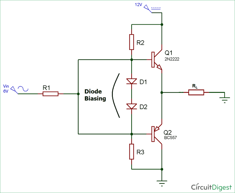
Push-Pull Amplifier is a power amplifier which is used to supply high power to the load. It consists of two transistors in which one is NPN and another is PNP. One transistor pushes the output on positive half cycle and other pulls on negative half cycle, this is why it is known as Push-Pull Amplifier. The advantage of Push-Pull amplifier is that there is no power dissipated in output transistor when signal is not present. There are three classification of Push-Pull Amplifier but generally Class B Amplifier is considered as Push Pull Amplifier.
Class A amplifier
Class B amplifier
Class AB amplifier
Class A Amplifier
Class A configuration is the most common power amplifier configuration. It consists of only one switching transistor which is set to remain ON always. It produces minimum distortion and maximum amplitude of output signal. The efficiency of Class A amplifier is very low near to 30%. The stages of the Class A amplifier allows same amount of load current to flow through it even when there is not input signal connected, therefore large heatsinks are needed for the output transistors. The circuit diagram for Class A amplifier is given below:
Class A Push Pull Amplifier Circuit Diagram
Class B Amplifier
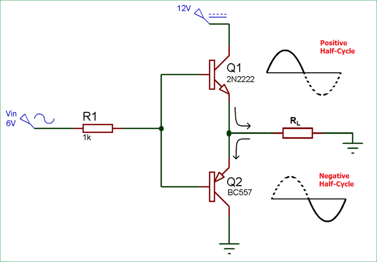
Class B amplifier is the actual Push-Pull Amplifier. Efficiency of Class B amplifier is higher than Class A amplifier, as it consists of two transistors NPN and PNP. The Class B amplifier circuit is biased in such a way that each transistor will work on one half cycle of the input waveform. Therefore, the conduction angle of this type of amplifier circuit is 180 Degree. One transistor pushes the output on positive half cycle and other pulls on negative half cycle, this is why it is known as Push-Pull Amplifier. Circuit diagram for Class B amplifier is given below:
Class B Push Pull Amplifier Circuit Diagram
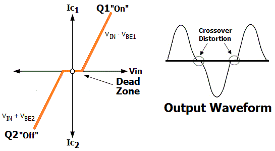
Class B generally suffers from an effect known as Crossover Distortion in which signal get distorted at 0V. We know that, a transistor requires 0.7v at its base-emitter junction to turn it on. So when AC input voltage is applied to push-pull amplifier, it starts increasing from 0 and until it reaches to 0.7v, transistor remains in OFF state and we don’t get any output. Same thing happen with PNP transistor in negative half cycle of AC wave, this is called Dead Zone. To overcome this problem, diodes are used for biasing, and then the amplifier is known as Class AB Amplifier.
Class AB Amplifier
A common method to remove that crossover distortion in Class B amplifier is to bias both the transistor at a point slightly above then the cut-off point of transistor. Then this circuit is known as Class AB amplifier circuit. Crossover distortion is later explained in this article.
Class AB Push Pull Amplifier Circuit Diagram
The Class AB amplifier circuit is the combination of both Class A and Class B amplifier. By adding the diode, transistors are biased in slightly conducting state even when no signal is present at base terminal, thus removing the crossover distortion problem.
Materials Required
Transformer (6-0-6)
BC557-PNP Transistor
2N2222-NPN Transistor
Resistor – 1k (2 nos)
LED
Working of Push-Pull Amplifier Circuit
The schematic diagram for Push-Pull amplifier circuit consists of two transistor Q1 and Q2 which are NPN and PNP respectively. When the input signal is positive Q1 starts conducting and produce a replica of the positive input at the output. At this moment Q2 remains in off condition.
Here, in this condition
VOUT = VIN – VBE1
Similarly, when input signal is negative Q1 turns off and Q2 starts conducting and produce a replica of the negative input at the output.
In this condition,
VOUT = VIN + VBE2
Now why the crossover distortion is happening when VIN reaches to zero? Let me show you rough characteristics diagram and output wave form of Push-Pull Amplifier Circuit.
Push-Pull Amplifier Circuit Output Waveform
Transistor Q1 and Q2 cannot be simultaneously ON, for Q1 to be on we require that VIN must be greater than Vout and for Q2 Vin must be less than Vout. If VIN is equal to zero then Vout must also be equal to zero.
Now when VIN is increasing from zero, the output voltage Vout will remain zero until VIN is less than VBE1 (which is approx. 0.7v), where VBE is the voltage required to turn on the NPN transistor Q1. Hence, the output voltage is exhibiting a dead zone during the period VIN is less than VBE or 0.7v. This same thing will happen when VIN is decreasing from zero, PNP transistor Q2 won’t conduct until the VIN is greater than VBE2 (~0.7v), where VBE2 is the voltage required to turn ON transistor Q2.


Pankaj Khatri
Author

Sunday, June 16, 2024

Capacitor blocks DC and allows AC


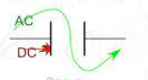
Before you understand why capacitor blocks DC and allows AC, you'll have to understand what is a capacitor! It is essentially two electrical conductors separated by a dielectric (insulator). If you add DC to the plates of the electric conductor plates, the dielectric acts as an open switch. Electricity will not pass thru it but the plates will be charged with +ve and -ve voltages respectively. AC current on the other hand, the polarity changes regularly between positive and negative on the plates (AC Signal +ve/-ve sign wave). Capacitors are repeatedly charged and discharged as the current's polarity alternates, allowing AC current to flow through. 

Mathematically, capacitive reactance (resistance) of a capacitor is calculated using this formula: XC = 1/(2πfC) - notice the f (frequency) in the formula and it is in the denominator? DC has 0 frequency thus the capacitive reactance XC will be 0 (open circuit - no current flows, AC has frequency greater than 0, eg 60Hz or 50 HZ etc (so the denominator will never be 0, which means the capacitive reactance, XC, in the formula will never be zero also the voltage applied to the capacitor divided by the non-zero value of capacitive reactance XC will result in a current flow


Elytrolytic Capacitor

Electrolyte -  AL +  AL2O3 + AL 

Each capacitor has 3 elements: ESL+ ESR + C where:
ESL - Inductive Element
ESR - Equivalent Series Resistance (capacitance Loss and Voltage ripples)
C - Capacitance

Safety in Electrolytic Capacitors

Electrolytic capacitor has a pressure valve untop of the cap. It is a cross pressure valve and trangular pressure valve (like benz's logo)

Do NOT connect the polarity in reverse otherwise the capacitor will overheat and explode

If the polarity is reverse, leakage current flows in the capacitor, which generates gas inside, internal pressure increases cause the pressure valve to open and the electrolyte spills out


Leak - DC Leak

Types of Capacitors

Bumble 
Mica Capacitor (ossilator/RF circuit)
Cirmamic - no in ossicalisator, 
Polipropatine - Audio amp /Coupling 
Newer Style Cermaic
Polistime very sensive to temp

Friday, June 14, 2024

Bipolar Transistor

 Bipolar Transistor

The common emitter amplifier configuration produces the highest current and power gain of all the three bipolar transistor configurations. 


  • Common Base Configuration   –   has Voltage Gain but no Current Gain.
  • Common Emitter Configuration   –   has both Current and Voltage Gain.
  • Common Collector Configuration   –   has Current Gain but no Voltage Gain.


The Bipolar Junction Transistor is a semiconductor device which can be used for switching or amplification

Unlike semiconductor diodes which are made up from two pieces of semiconductor material to form one simple pn-junction. The bipolar transistor uses one more layer of semiconductor material to produce a device with properties and characteristics of an amplfier.

If we join together two individual signal diodes back-to-back, this will give us two PN-junctions connected together in series which would share a common Positve, (P) or Negative, (N) terminal. The fusion of these two diodes produces a three layer, two junction, three terminal device forming the basis of a Bipolar Junction Transistor, or BJT for short.

Transistors are three terminal active devices made from different semiconductor materials that can act as either an insulator or a conductor by the application of a small signal voltage. The transistor’s ability to change between these two states enables it to have two basic functions: “switching” (digital electronics) or “amplification” (analogue electronics). Then bipolar transistors have the ability to operate within three different regions:

Active Region   –   the transistor operates as an amplifier and Ic = β*Ib
Saturation   –   the transistor is “Fully-ON” operating as a switch and Ic = I(saturation)
Cut-off   –   the transistor is “Fully-OFF” operating as a switch and Ic = 0

bipolar transistor

A Typical
Bipolar Transistor

The word Transistor is a combination of the two words Transfer Varistor which describes their mode of operation way back in their early days of electronics development. There are two basic types of bipolar transistor construction, PNP and NPN, which basically describes the physical arrangement of the P-type and N-type semiconductor materials from which they are made.

The Bipolar Transistor basic construction consists of two PN-junctions producing three connecting terminals with each terminal being given a name to identify it from the other two. These three terminals are known and labelled as the Emitter ( E ), the Base ( B ) and the Collector ( C ) respectively.
Bipolar Transistors are current regulating devices that control the amount of current flowing through them from the Emitter to the Collector terminals in proportion to the amount of biasing voltage applied to their base terminal, thus acting like a current-controlled switch. As a small current flowing into the base terminal controls a much larger collector current forming the basis of transistor action.
The principle of operation of the two transistor types PNP and NPN, is exactly the same the only difference being in their biasing and the polarity of the power supply for each type.

Bipolar Transistor Construction

bipolar transistor construction

The construction and circuit symbols for both the PNP and NPN bipolar transistor are given above with the arrow in the circuit symbol always showing the direction of “conventional current flow” between the base terminal and its emitter terminal. The direction of the arrow always points from the positive P-type region to the negative N-type region for both transistor types, exactly the same as for the standard diode symbol.

Bipolar Transistor Configurations

As the Bipolar Transistor is a three terminal device, there are basically three possible ways to connect it within an electronic circuit with one terminal being common to both the input and output signals. Each method of connection responding differently to its input signal within a circuit as the static characteristics of the transistor vary with each circuit arrangement.

  • Common Base Configuration   –   has Voltage Gain but no Current Gain.
  • Common Emitter Configuration   –   has both Current and Voltage Gain.
  • Common Collector Configuration   –   has Current Gain but no Voltage Gain.

The Common Base (CB) Configuration

As its name suggests, in the Common Base or grounded base configuration, the BASE connection is common to both the input signal AND the output signal. The input signal is applied between the transistors base and the emitter terminals, while the corresponding output signal is taken from between the base and the collector terminals as shown. The base terminal is grounded or can be connected to some fixed reference voltage point.

The input current flowing into the emitter is quite large as its the sum of both the base current and collector current respectively therefore, the collector current output is less than the emitter current input resulting in a current gain for this type of circuit of “1” (unity) or less, in other words the common base configuration “attenuates” the input signal.

The Common Base Transistor Circuit

common base configuration

This type of amplifier configuration is a non-inverting voltage amplifier circuit, in that the signal voltages Vin and Vout are “in-phase”. This type of transistor arrangement is not very common due to its unusually high voltage gain characteristics. Its input characteristics represent that of a forward biased diode while the output characteristics represent that of an illuminated photo-diode. 

Also this type of bipolar transistor configuration has a high ratio of output to input resistance or more importantly “load” resistance ( RL ) to “input” resistance ( Rin ) giving it a value of “Resistance Gain”. Then the voltage gain ( Av ) for a common base configuration is therefore given as:

Common Base Voltage Gain

common base transistor gain

Where: Ic/Ie is the current gain, alpha ( α ) and RL/Rin is the resistance gain.

The common base circuit is generally only used in single stage amplifier circuits such as microphone pre-amplifier or radio frequency (  ) amplifiers due to its very good high frequency response.

The Common Emitter (CE) Configuration

In the Common Emitter or grounded emitter configuration, the input signal is applied between the base and the emitter, while the output is taken from between the collector and the emitter as shown. This type of configuration is the most commonly used circuit for transistor based amplifiers and which represents the “normal” method of bipolar transistor connection.

The common emitter amplifier configuration produces the highest current and power gain of all the three bipolar transistor configurations. This is mainly because the input impedance is LOW as it is connected to a forward biased PN-junction, while the output impedance is HIGH as it is taken from a reverse biased PN-junction.

The Common Emitter Amplifier Circuit

common emitter configuration

In this type of configuration, the current flowing out of the transistor must be equal to the currents flowing into the transistor as the emitter current is given as Ie = Ic + Ib.

As the load resistance ( RL ) is connected in series with the collector, the current gain of the common emitter transistor configuration is quite large as it is the ratio of Ic/Ib. A transistors current gain is given the Greek symbol of Beta, ( β ).

As the emitter current for a common emitter configuration is defined as Ie = Ic + Ib, the ratio of Ic/Ie is called Alpha, given the Greek symbol of α. Note: that the value of Alpha will always be less than unity.

Since the electrical relationship between these three currents, IbIc and Ie is determined by the physical construction of the transistor itself, any small change in the base current ( Ib ), will result in a much larger change in the collector current ( Ic ).

Then, small changes in current flowing in the base will thus control the current in the emitter-collector circuit. Typically, Beta has a value between 20 and 200 for most general purpose transistors. So if a transistor has a Beta value of say 100, then one electron will flow from the base terminal for every 100 electrons flowing between the emitter-collector terminal.

By combining the expressions for both Alphaα and Betaβ the mathematical relationship between these parameters and therefore the current gain of the transistor can be given as:

bipolar transistor alpha beta relationship

common emitter current gain

Where: “Ic” is the current flowing into the collector terminal, “Ib” is the current flowing into the base terminal and “Ie” is the current flowing out of the emitter terminal.

Then to summarise a little. This type of bipolar transistor configuration has a greater input impedance, current and power gain than that of the common base configuration but its voltage gain is much lower. The common emitter configuration is an inverting amplifier circuit. This means that the resulting output signal has a 180o phase-shift with regards to the input voltage signal.

The Common Collector (CC) Configuration

In the Common Collector or grounded collector configuration, the collector is connected to ground through the supply, thus the collector terminal is common to both the input and the output. The input signal is connected directly to the base terminal, while the output signal is taken from across the emitter load resistor as shown. This type of configuration is commonly known as a Voltage Follower or Emitter Follower circuit.

The common collector, or emitter follower configuration is very useful for impedance matching applications because of its very high input impedance, in the region of hundreds of thousands of Ohms while having a relatively low output impedance.

The Common Collector Transistor Circuit

common collector configuration

The common emitter configuration has a current gain approximately equal to the β value of the transistor itself. However in the common collector configuration, the load resistance is connected in series with the emitter terminal so its current is equal to that of the emitter current.

As the emitter current is the combination of the collector AND the base current combined, the load resistance in this type of transistor configuration also has both the collector current and the input current of the base flowing through it. Then the current gain of the circuit is given as:

The Common Collector Current Gain

common collector gain

Common Collector Current Gain

This type of bipolar transistor configuration is a non-inverting circuit in that the signal voltages of Vin and Vout are “in-phase”. The common collector configuration has a voltage gain of about “1” (unity gain). Thus it can considered as a voltage-buffer since the voltage gain is unity.

The load resistance of the common collector transistor receives both the base and collector currents giving a large current gain (as with the common emitter configuration) therefore, providing good current amplification with very little voltage gain.

Having looked at the three different types of bipolar transistor configurations, we can now summarise the various relationships between the transistors individual DC currents flowing through each leg and its DC current gains given above in the following table.

Relationship between DC Currents and Gains

transistor currentstransistor alpha and beta equations
transistor base currents
transistor collector currentstransistor emitter currents

Note that although we have looked at NPN Bipolar Transistor configurations here, PNP transistors are just as valid to use in each configuration as the calculations will all be the same, as for the non-inverting of the amplified signal. The only difference will be in the voltage polarities and current directions.

Bipolar Transistor Summary

Then to summarise, the behaviour of the bipolar transistor in each one of the above circuit configurations is very different and produces different circuit characteristics with regards to input impedance, output impedance and gain whether this is voltage gain, current gain or power gain and this is summarised in the table below.

Bipolar Transistor Configurations

bipolar transistor configurations

with the generalised characteristics of the different transistor configurations given in the following table:

CharacteristicCommon
Base
Common
Emitter
Common
Collector
Input ImpedanceLowMediumHigh
Output ImpedanceVery HighHighLow
Phase Shift0o180o0o
Voltage GainHighMediumLow
Current GainLowMediumHigh
Power GainLowVery HighMedium

In the next tutorial about Bipolar Transistors, we will look at the NPN Transistor in more detail when used in the common emitter configuration as an amplifier as this is the most widely used configuration due to its flexibility and high gain. We will also plot the output characteristics curves commonly associated with amplifier circuits as a function of the collector current to the base current.

Bipolar power supply

  Dual 12V Power Supply Mini Board , provides a quick and easy solution to providing a dual or split power source. These units operate from ...